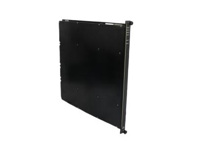
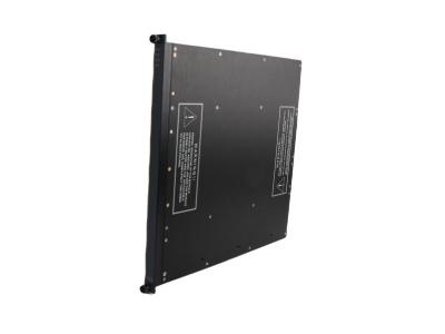
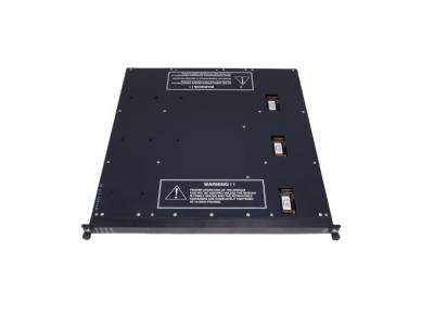
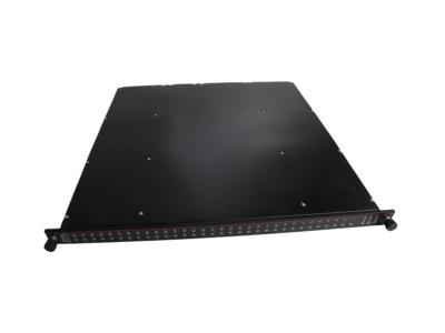
3601E Product datasheet
|
Model number: |
3601E |
|
Module Type: |
Digital Output Module |
|
Manufacture: |
Triconex |
|
Condition: |
Brand New |
|
Range of Product: |
Tricon System |
|
Lead time: |
In Stock |
|
Weight: |
2.04kg |
|
HS CODE: |
8537101190 |
|
Dimension: |
2.2x40.5x40cm |
|
MOQ: |
1 |
|
Product Origin: |
USA |
|
System: |
DCS |
|
Discontinued on: |
active |
|
Communication Service: |
Ethernet router |
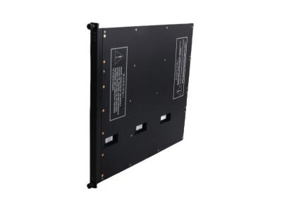
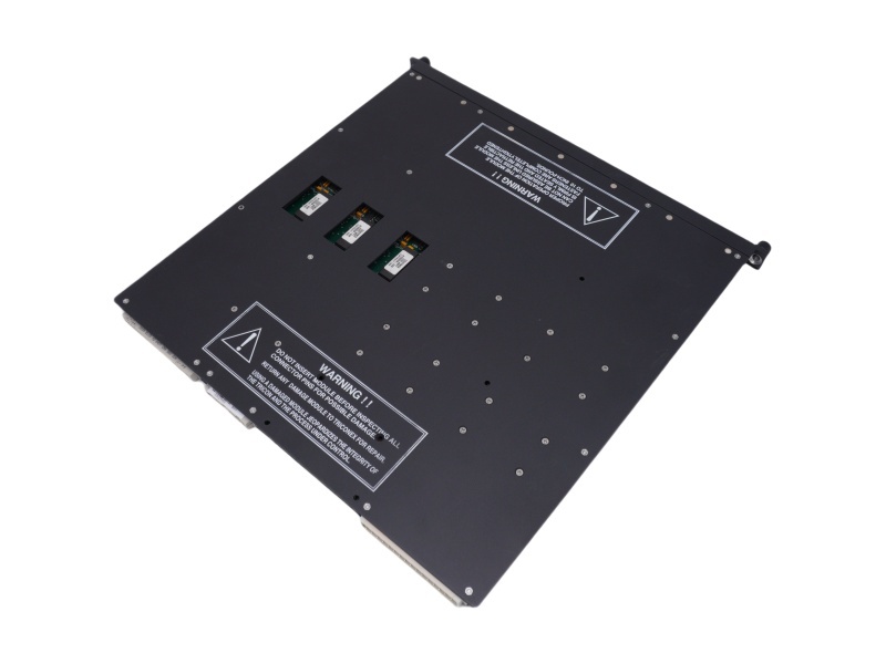
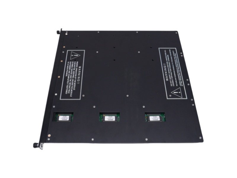
3601E Functional Description
If you have other request contact our team to get customized service


 Call +86 18159889985 to be connected with our Manager Stella
 Email to sales6@apterpower.com get your best quotation
 For the quick assistance message us on WhatsApp at +86 18159889985 now!
|
Triconex |
3805EN |
Triconex |
3625A |
Triconex |
3008 |
|
Triconex |
3805E |
Triconex |
3625 |
Triconex |
3006 |
|
Triconex |
3721 |
Triconex |
3604E |
Triconex |
MP3101 |
|
Triconex |
3708E |
Triconex |
3601E |
Triconex |
RO3451 |
|
Triconex |
3706A |
Triconex |
3533E |
Triconex |
HCU3700/3703E |
|
Triconex |
3703E |
Triconex |
3511 |
Triconex |
EMPII 3006 |
|
Triconex |
3700A |
Triconex |
3510 |
Triconex |
DO3201 |
|
Triconex |
3664 |
Triconex |
3503E |
Triconex |
DI3301 |
|
Triconex |
3636R |
Triconex |
3502EN2 |
Triconex |
CM2201 7400206-100 |
|
Triconex |
3625N |
Triconex |
3008N |
Triconex |
AI3351 |
Tricon System Introduction
The Tricon is a state-of-the art controller that provides fault tolerance by means of Triple-Modular Redundant (TMR) architecture. TMR integrates three isolated, parallel control systems and extensive diagnostics in one control system. The system uses two-out-ofthree voting to provide high-integrity, error-free, uninterrupted process operation with no single point of failure.
The Tricon controller uses three identical channels. Each channel independently executes the control program in parallel with the other two channels. Specialized hardware/software voting mechanisms qualify and verify all digital inputs and outputs from the field, while analog inputs are subject to a mid-value selection process. Because each channel is isolated from the others, no single-point failure in any channel can pass to another. If a hardware failure does occur on one channel, the other channels override it. Meanwhile the faulting module can easily be removed and replaced while thecontroller is online without interrupting the process. Setting up control programs is simplified with the triplicated Tricon system, because it operates as a single control system from the user’s point of view. The user terminates sensors and actuators at a single wiring terminal andprograms the Tricon with one set of control program logic.
The Tricon controller manages the rest! Extensive diagnostics on each channel, module, and functional circuit immediately detect and report operational faults by means of indicators or alarms.
TMR Digital Output Modules
TMR Digital Output Modules A TMR digital output (DO) module receives output signals from the main processors on each of three channels. Each set of three signals is then voted by special quadruplicated output circuitry on the module. The circuitry produces one voted output signal and passes it to the field termination. The quadruplicated voter circuitry provides multiple redundancy for all critical signal paths, guaranteeing safety and maximum availability. Each TMR digital output module has a voltage-loopback circuit which verifies the operation of each output switch independently of the presence of a load and determines whether latent faults exist. Failure of the detected field voltage to match the commanded state of the output point activates the LOAD/FUSE alarm indicator.
In addition, ongoing diagnostics are performed on each channel and circuit of a TMR digital output module. Failure of any diagnostic on any channel activates the Fault indicator, which in turn activates the chassis alarm signal. The Fault indicator merely indicates a channel fault, not a module failure. The module is guaranteed to operate properly in the presence of a single fault and may continue to operate properly with certain kinds of multiple faults.
All TMR digital output modules support hot-spare capability, and require a separate external termination panel (ETP) with a cable interface to the Tricon backplane. Each module is mechanically keyed to prevent improper installation in a configured chassis. Digital outputs are designed to source the current to field devices, so field power must be wired to each output point on the field termination.