531X121PCRALG1 Product datasheet
|
Model number: |
531X121PCRALG1 |
|
Module Type: |
Power Connect Card |
|
Manufacture: |
GE |
|
Condition: |
Brand New |
|
Range of Product: |
Multilin |
|
Lead time: |
In Stock |
|
Weight: |
0.06 kg |
|
HS CODE: |
8537101190 |
|
Dimension: |
11.3x5.7x1.5cm |
|
MOQ: |
1 |
|
Product Origin: |
USA |
|
System: |
DCS |
|
Discontinued on: |
Active |
|
Communication Service: |
Ethernet router |
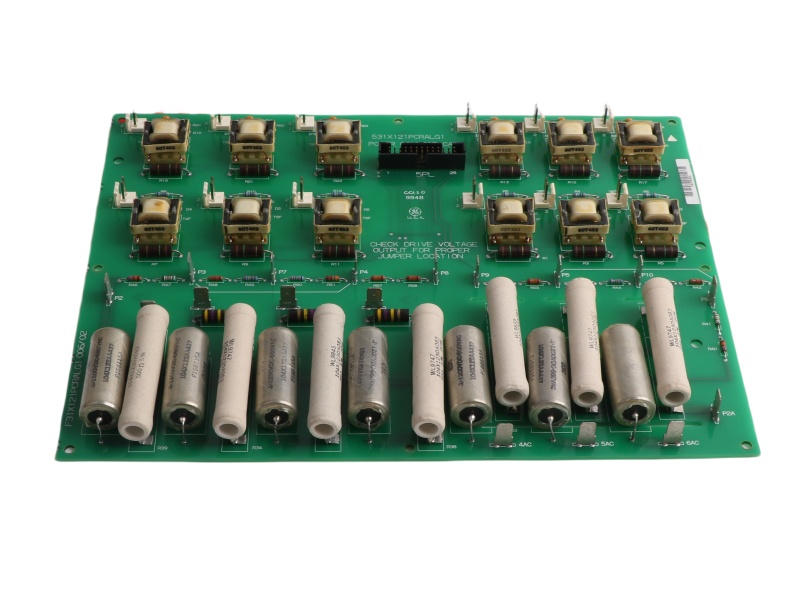
531X121PCRALG1 Functional Description
The GE Power Connection Board 531X121PCRALG1 is a replacement component designed for various original equipment power connection boards. This board ensures seamless integration and easy troubleshooting, thanks to the built-in diagnostic tools available in the drive system. When diagnosing performance issues, the 531X121PCRALG1 assists in identifying faulty components and predicting potential failures. These insights allow users to optimize the drive’s operation by adjusting configurations for improved efficiency.
GE 531X121PCRALG1 High-Performance Power Supply Card To diagnose issues while the drive remains powered and operational, navigate to the control panel, access the diagnostic tools menu, and initiate the scan. The generated report details system performance and potential malfunctions. For easier analysis, users can view results on the control panel or download them to a laptop for in-depth review. Given the extensive data, using a laptop is often more convenient for storage and future reference.
If the 531X121PCRALG1 Power Connect Card is confirmed to be defective, ordering a replacement is straightforward. Upon delivery, inspect the shipping label before opening the carton. Verify that the part number matches the ordered 531X121PCRALG1 Drive System Power Connect Card and document the serial and catalog numbers for record-keeping. Proper documentation ensures efficient maintenance and helps track the board’s history. With accurate diagnostics and correct installation, the 531X121PCRALG1 contributes to reliable drive operation and long-term performance.
If you have other request contact our team to get customized service


 Call +86 18159889985 to be connected with our Manager Stella
 Email to sales6@apterpower.com get your best quotation
 For the quick assistance message us on WhatsApp at +86 18159889985 now!
|
GE |
531X306LCCBFM1 |
GE |
531X139APMASM7 |
GE |
531X111PSHAPG3 |
|
GE |
531X307LTBAJG1 |
GE |
531X152IOCAKG1 |
GE |
531X111PSHARG1 |
|
GE |
531X305NTBAPG1 |
GE |
531X160HFCACG1 |
GE |
531X111PSHARG3 |
|
GE |
531X305NTBANG1 |
GE |
531X175SSBAAM3 |
GE |
531X113PSFARG1 |
|
GE |
531X305NTBACG1 |
GE |
531X171TMAAFG2 |
GE |
531X121PCRALG1 |
|
GE |
531X303MCPBCG1 |
GE |
531X175SSBAYM2 |
GE |
531X123PCHACG1 |
|
GE |
531X304IBDANG1 |
GE |
531X179PLMAKG1 |
GE |
DS200CPCAG1ABB |
|
GE |
531X300CCHAGM5 |
GE |
531X189LTBALG1 |
GE |
531X124MSDAJG2 |
|
GE |
531X300CCHAFM5 |
GE |
531X191RTBAJG1 |
GE |
531X126SNDAFG1 |
|
GE |
531X207LCSAMG1 |
GE |
531X307LTBAJG1 |
GE |
531X128HMSADG1 |
GE Gas Turbine Control System
The GE Mark VI system is a comprehensive control solution used primarily in power generation and other industrial applications. It controls, protects, and monitors gas and steam turbines, generators, and auxiliary systems.
The SPEEDTRONIC™ Mark VI turbine control is the current state-of-the-art control for GE turbines that have a heritage of more than 30 years of successful operation. It is designed as a complete integrated control, protection, and monitoring system for generator and mechanical drive applications of gas and steam turbines. It is also an ideal platform for integrating all power island and balance-of-plant controls. Hardware and software are designed with close coordination between GE’s turbine design engineering and controls engineering to insure that your control system provides the optimum turbine performance and you receive a true “system” solution. With Mark VI, you receive the benefits of GE’s unmatched experience with an advanced turbine control platform.
The heart of the control system is the Control Module, which is available in either a 13- or 21- slot standard VME card rack. Inputs are received by the Control Module through termination boards with either barrier or box-type terminal blocks and passive signal conditioning. Each I/O card contains a TMS320C32 DSP processor to digitally filter the data before conversion to 32 bit IEEE-854 floating point format. The data is then placed in dual port memory that is accessible by the on-board C32 DSP on one side and the VME bus on the other. In addition to the I/O cards, the Control Module contains an “internal” communication card, a main processor card, and sometimes a flash disk card. Each card takes one slot except for the main processor that takes two slots. Cards are manufactured with surface-mounted technology and conformal coated per IPC-CC830. I/O data is transmitted on the VME backplane between the I/O cards and the VCMI card located in slot 1. The VCMI is used for “internal” communications between:
■ I/O cards that are contained within its card rack
■ I/O cards that may be contained in expansion I/O racks called Interface Modules
■ I/O in backup <P> Protection Modules
■ I/O in other Control Modules used in triple redundant control configurations
■ The main processor card
Triple Redundancy
Mark VI control systems are available in Simplex and Triple Redundant forms for small applications and large integrated systems with control ranging from a single module to many distributed modules. The name Triple Module Redundant (TMR) is derived from the basic architecture with three completely separate and independent Control Modules, power supplies, and IONets. Mark VI is the third generation of triple redundant control systems that were pioneered by GE in 1983. System throughput enables operation of up to nine, 21-slot VME racks of I/O cards at 40 ms including voting the data. Inputs are voted in software in a scheme called Software Implemented Fault Tolerance (SIFT). The VCMI card in each Control Module receives inputs from the Control Module back-plane and other modules via “its own” IONet. Data from the VCMI cards in each of the three Control Modules is then exchanged and voted prior to transmitting the data to the main processor cards for execution of the application software. Output voting is extended to the turbine with three coil servos for control valves and 2 out of 3 relays for critical outputs such as hydraulic trip solenoids. Other forms of output voting are available, including a median select of 4-20ma outputs for process control and 0- 200ma outputs for positioners. Sensor interface for TMR controls can be either single, dual, triple redundant, or combinations of redundancy levels. The TMR architecture supports riding through a single point failure in the electronics and repair of the defective card or module while the process is running. Adding sensor redundancy increases the fault tolerance of the overall “system.” Another TMR feature is the ability to distinguish between field sensor faults and internal electronics faults. Diagnostics continuously monitor the 3 sets of input electronics and alarms any discrepancies between them as an internal fault versus a sensor fault. In addition, all three main processors
continue to execute the correct “voted” input data,More info pls check GEH-6005 datasheet