DS200DMCBG1AJE Product datasheet
|
Model number: |
DS200DMCBG1AJE |
|
Module Type: |
DOS DUP Processor Board |
|
Manufacture: |
GE |
|
Condition: |
Brand New |
|
Range of Product: |
EX2100 |
|
Lead time: |
In Stock |
|
Weight: |
0.64 kg |
|
HS CODE: |
8537101190 |
|
Dimension: |
28x21.4x3.3cm |
|
MOQ: |
1 |
|
Product Origin: |
USA |
|
System: |
DCS |
|
Discontinued on: |
Active |
|
Communication Service: |
Ethernet router |
DS200DMCBG1AJE Functional Description
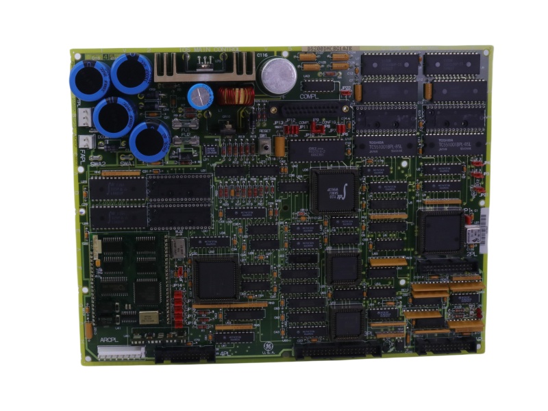
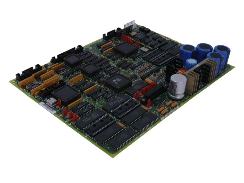
The DS200DMCBG1AJE printed circuit board (PCB) from General Electric is a key component in their Mark V Turbine Control System Series, specifically designed for use in automated drive assemblies for wind, gas, and steam turbines. As indicated by its extended name, the DS200DMCBG1AJE is part of the Mark V Series, which has been pivotal in turbine management and control. Despite its critical role, the General Electric DS200DMCBG1AJE is considered obsolete, as General Electric ceased production of this product in the years following its initial release. Nevertheless, the Mark V Series, including the DS200DMCBG1AJE, remains a highly respected product line, marking one of the last to utilize General Electric's patented Speedtronic control system technology.
In terms of hardware specifications, the DS200DMCBG1AJE DOS DUP Processor Board features three 26-pin connectors, one 40-pin connector, and 19 jumpers, along with two LEDs, labeled CR2 and CR12. These LEDs are essential for monitoring the board’s processing activity and offer users a quick diagnostic tool. When troubleshooting, inspecting the LEDs for activity can provide immediate insights into the board’s operational status. It's important to note that the DS200DMCBG1AJE is a revised version of the original DOS DUP Processor Board in the Mark V Series. The earlier iteration, the DS200DMCBG1, lacks the revisions—A, J, and E—that the DS200DMCBG1AJE incorporates. Furthermore, voltage suppression in the Mark V Series is typically managed by a group of hardware components, such as diodes, rectifiers, capacitors, and resistors, which are standardized across the DS200DMCBG1AJE product line.
This DS200DMCBG1AJE Mark VI PCB Board Assembly continues to be a reliable, though outdated, solution in turbine control systems.
If you have other request contact our team to get customized service


 Call +86 18159889985 to be connected with our Manager Stella
 Email to sales6@apterpower.com get your best quotation
 For the quick assistance message us on WhatsApp at +86 18159889985 now!
|
GE |
DS200CDBAG1ACA |
GE |
IS220YDOAS1AJ |
GE |
IS200VAICH1DAA |
|
GE |
DS200LDCCH1 |
GE |
IS200JPDMG1ADC |
GE |
IS200MVRBH1ACC |
|
GE |
DS200KLDCG1AAA |
GE |
IS200SRLYH2AAA |
GE |
IS220PAOCH1BE |
|
GE |
DS200KLDCG1A |
GE |
IS200SRTDH2ACB |
GE |
IS420ESWBH2A |
|
GE |
DS200KLDBG1A |
GE |
IS200SRLYH2AAA |
GE |
IS220PDIAH1A |
|
GE |
DS200KLDBG1ABC |
GE |
IS220PRTDH1A |
GE |
IS220PAOCH1A |
|
GE |
DS200GDPAG1A |
GE |
IS220YDIAS1AK |
GE |
IS215VPROH1BE |
|
GE |
IS200EXAMG1A |
GE |
IS200TBAIS1CED |
GE |
IS215VPROH1BH |
|
GE |
DS2020FECNRX010A |
GE |
IS200TRLYS1BGG |
GE |
IS200VAICH1DBC |
|
GE |
DS200FSAAG1ABA |
GE |
IS200VAICH1D |
GE |
IS200VAICH1DAB |
GE Gas Turbine Control System
The GE Mark VI system is a comprehensive control solution used primarily in power generation and other industrial applications. It controls, protects, and monitors gas and steam turbines, generators, and auxiliary systems.
The SPEEDTRONIC™ Mark VI turbine control is the current state-of-the-art control for GE turbines that have a heritage of more than 30 years of successful operation. It is designed as a complete integrated control, protection, and monitoring system for generator and mechanical drive applications of gas and steam turbines. It is also an ideal platform for integrating all power island and balance-of-plant controls. Hardware and software are designed with close coordination between GE’s turbine design engineering and controls engineering to insure that your control system provides the optimum turbine performance and you receive a true “system” solution. With Mark VI, you receive the benefits of GE’s unmatched experience with an advanced turbine control platform.
The heart of the control system is the Control Module, which is available in either a 13- or 21- slot standard VME card rack. Inputs are received by the Control Module through termination boards with either barrier or box-type terminal blocks and passive signal conditioning. Each I/O card contains a TMS320C32 DSP processor to digitally filter the data before conversion to 32 bit IEEE-854 floating point format. The data is then placed in dual port memory that is accessible by the on-board C32 DSP on one side and the VME bus on the other. In addition to the I/O cards, the Control Module contains an “internal” communication card, a main processor card, and sometimes a flash disk card. Each card takes one slot except for the main processor that takes two slots. Cards are manufactured with surface-mounted technology and conformal coated per IPC-CC830. I/O data is transmitted on the VME backplane between the I/O cards and the VCMI card located in slot 1. The VCMI is used for “internal” communications between:
■ I/O cards that are contained within its card rack
■ I/O cards that may be contained in expansion I/O racks called Interface Modules
■ I/O in backup <P> Protection Modules
■ I/O in other Control Modules used in triple redundant control configurations
■ The main processor card
Triple Redundancy
Mark VI control systems are available in Simplex and Triple Redundant forms for small applications and large integrated systems with control ranging from a single module to many distributed modules. The name Triple Module Redundant (TMR) is derived from the basic architecture with three completely separate and independent Control Modules, power supplies, and IONets. Mark VI is the third generation of triple redundant control systems that were pioneered by GE in 1983. System throughput enables operation of up to nine, 21-slot VME racks of I/O cards at 40 ms including voting the data. Inputs are voted in software in a scheme called Software Implemented Fault Tolerance (SIFT). The VCMI card in each Control Module receives inputs from the Control Module back-plane and other modules via “its own” IONet. Data from the VCMI cards in each of the three Control Modules is then exchanged and voted prior to transmitting the data to the main processor cards for execution of the application software. Output voting is extended to the turbine with three coil servos for control valves and 2 out of 3 relays for critical outputs such as hydraulic trip solenoids. Other forms of output voting are available, including a median select of 4-20ma outputs for process control and 0- 200ma outputs for positioners. Sensor interface for TMR controls can be either single, dual, triple redundant, or combinations of redundancy levels. The TMR architecture supports riding through a single point failure in the electronics and repair of the defective card or module while the process is running. Adding sensor redundancy increases the fault tolerance of the overall “system.” Another TMR feature is the ability to distinguish between field sensor faults and internal electronics faults. Diagnostics continuously monitor the 3 sets of input electronics and alarms any discrepancies between them as an internal fault versus a sensor fault. In addition, all three main processors
continue to execute the correct “voted” input data,More info pls check GEH-6005 datasheet