DS200TCQAG1BHF Product datasheet
|
Model number: |
DS200TCQAG1BHF |
|
Module Type: |
Extended Analog I/O Board |
|
Manufacture: |
GE |
|
Condition: |
Brand New |
|
Range of Product: |
Mark VIE |
|
Lead time: |
In Stock |
|
Weight: |
0.22 kg |
|
HS CODE: |
8537101190 |
|
Dimension: |
2.1x18.6x26.3cm |
|
MOQ: |
1 |
|
Product Origin: |
USA |
|
System: |
DCS |
|
Discontinued on: |
Active |
|
Communication Service: |
Ethernet router |
DS200TCQAG1BHF Functional Description
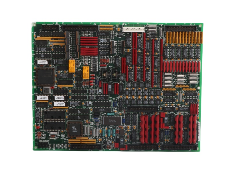
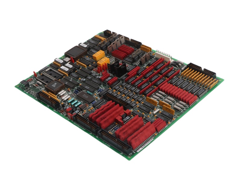
The DS200TCQAG1BHF Analog I/O Board from General Electric is designed for use in the Mark V Series of turbine control systems. This board, like others in the Mark V Series, incorporates essential and unique hardware elements to deliver reliable functionality. Before purchasing the GE Speedtronic EX2100 Excitation Control DS200TCQAG1BHF, it's important to note that it utilizes a variety of product revisions, including both an H-rated secondary functional revision and an F-rated artwork revision, ensuring compatibility and performance.
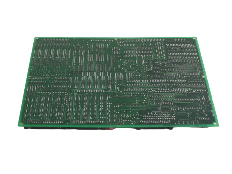
The DS200TCQAG1BHF RST Extended Analog I/O Board features four 34-pin connectors, two 40-pin connectors, and six jumpers, with six LEDs for status indication. The board is designed with six mounting holes to securely install it in the board cabinet of the drive. These holes align with the board rack, allowing for easy attachment using screws and washers. It’s essential to keep washers and screws intact when removing the old board, as they are needed for installing the replacement. Caution is required to avoid dropping metal parts, such as screws or washers, into the cabinet, as they can cause damage, electrical shock, or even fires if the drive is powered up with these parts inside.
To safely handle the board, it’s recommended to hold the screwdriver with one hand and use the other hand to secure the screw during removal. For installation, align the screw with the hole and tighten gently—never over-tighten, as this could crack the board. The washers help prevent damage from excess tightening, ensuring the board remains securely in place without causing harm. The General Electric DS200TCQAG1BHF Analog I/O Board is crucial for maintaining the proper function of your turbine control system.
If you have other request contact our team to get customized service


 Call +86 18159889985 to be connected with our Manager Stella
 Email to sales6@apterpower.com get your best quotation
 For the quick assistance message us on WhatsApp at +86 18159889985 now!
|
GE |
IS200TRLYH1BHH |
GE |
IS220YDOAS1AJ |
GE |
IS200VAICH1DAA |
|
GE |
IS420UCSBH3A |
GE |
IS200JPDMG1ADC |
GE |
IS200MVRBH1ACC |
|
GE |
IS200TRLYH1BED |
GE |
IS200SRLYH2AAA |
GE |
IS220PAOCH1BE |
|
GE |
IS200TRLYH1BGG |
GE |
IS200SRTDH2ACB |
GE |
IS420ESWBH2A |
|
GE |
IS200TRLYH1BGE |
GE |
IS200SRLYH2AAA |
GE |
IS220PDIAH1A |
|
GE |
IS200TRLYH1BGF |
GE |
IS220PRTDH1A |
GE |
IS220PAOCH1A |
|
GE |
IS200TRLYH1BEC |
GE |
IS220YDIAS1AK |
GE |
IS215VPROH1BE |
|
GE |
IS200EXAMG1A |
GE |
IS200TBAIS1CED |
GE |
IS215VPROH1BH |
|
GE |
IS200TREGH1BDB |
GE |
IS200TRLYS1BGG |
GE |
IS200VAICH1DBC |
|
GE |
IS200TREGH1B |
GE |
IS200VAICH1D |
GE |
IS200VAICH1DAB |
GE Gas Turbine Control System
The GE Mark VI system is a comprehensive control solution used primarily in power generation and other industrial applications. It controls, protects, and monitors gas and steam turbines, generators, and auxiliary systems.
The SPEEDTRONIC™ Mark VI turbine control is the current state-of-the-art control for GE turbines that have a heritage of more than 30 years of successful operation. It is designed as a complete integrated control, protection, and monitoring system for generator and mechanical drive applications of gas and steam turbines. It is also an ideal platform for integrating all power island and balance-of-plant controls. Hardware and software are designed with close coordination between GE’s turbine design engineering and controls engineering to insure that your control system provides the optimum turbine performance and you receive a true “system” solution. With Mark VI, you receive the benefits of GE’s unmatched experience with an advanced turbine control platform.
The heart of the control system is the Control Module, which is available in either a 13- or 21- slot standard VME card rack. Inputs are received by the Control Module through termination boards with either barrier or box-type terminal blocks and passive signal conditioning. Each I/O card contains a TMS320C32 DSP processor to digitally filter the data before conversion to 32 bit IEEE-854 floating point format. The data is then placed in dual port memory that is accessible by the on-board C32 DSP on one side and the VME bus on the other. In addition to the I/O cards, the Control Module contains an “internal” communication card, a main processor card, and sometimes a flash disk card. Each card takes one slot except for the main processor that takes two slots. Cards are manufactured with surface-mounted technology and conformal coated per IPC-CC830. I/O data is transmitted on the VME backplane between the I/O cards and the VCMI card located in slot 1. The VCMI is used for “internal” communications between:
■ I/O cards that are contained within its card rack
■ I/O cards that may be contained in expansion I/O racks called Interface Modules
■ I/O in backup <P> Protection Modules
■ I/O in other Control Modules used in triple redundant control configurations
■ The main processor card
Triple Redundancy
Mark VI control systems are available in Simplex and Triple Redundant forms for small applications and large integrated systems with control ranging from a single module to many distributed modules. The name Triple Module Redundant (TMR) is derived from the basic architecture with three completely separate and independent Control Modules, power supplies, and IONets. Mark VI is the third generation of triple redundant control systems that were pioneered by GE in 1983. System throughput enables operation of up to nine, 21-slot VME racks of I/O cards at 40 ms including voting the data. Inputs are voted in software in a scheme called Software Implemented Fault Tolerance (SIFT). The VCMI card in each Control Module receives inputs from the Control Module back-plane and other modules via “its own” IONet. Data from the VCMI cards in each of the three Control Modules is then exchanged and voted prior to transmitting the data to the main processor cards for execution of the application software. Output voting is extended to the turbine with three coil servos for control valves and 2 out of 3 relays for critical outputs such as hydraulic trip solenoids. Other forms of output voting are available, including a median select of 4-20ma outputs for process control and 0- 200ma outputs for positioners. Sensor interface for TMR controls can be either single, dual, triple redundant, or combinations of redundancy levels. The TMR architecture supports riding through a single point failure in the electronics and repair of the defective card or module while the process is running. Adding sensor redundancy increases the fault tolerance of the overall “system.” Another TMR feature is the ability to distinguish between field sensor faults and internal electronics faults. Diagnostics continuously monitor the 3 sets of input electronics and alarms any discrepancies between them as an internal fault versus a sensor fault. In addition, all three main processors
continue to execute the correct “voted” input data,More info pls check GEH-6005 datasheet