IS200EMCSG1AA Product datasheet
|
Model number: |
IS200EMCSG1AA |
|
Module Type: |
Exciter Multibridge Conduction Sensor Card |
|
Manufacture: |
GE |
|
Condition: |
Brand New |
|
Range of Product: |
Mark VIE |
|
Lead time: |
In Stock |
|
Weight: |
0.22 kg |
|
HS CODE: |
8537101190 |
|
Dimension: |
2.1x18.6x26.3cm |
|
MOQ: |
1 |
|
Product Origin: |
USA |
|
System: |
DCS |
|
Discontinued on: |
Active |
|
Communication Service: |
Ethernet router |
IS200EMCSG1AA Functional Description
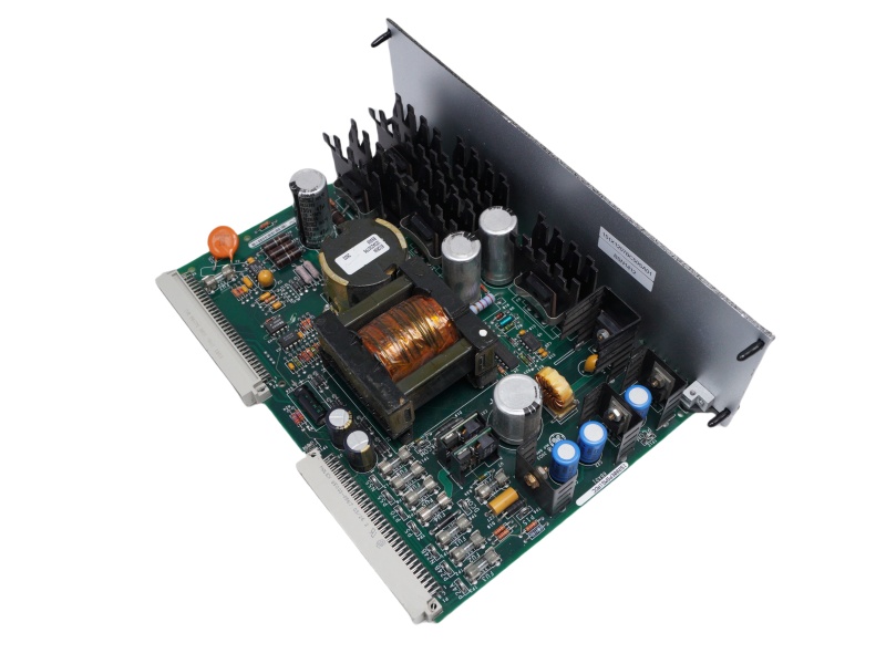
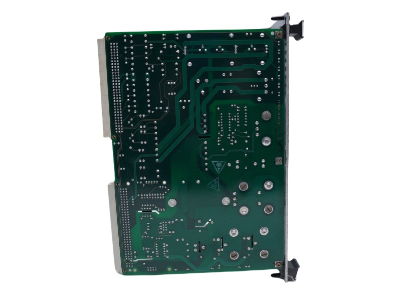
The IS200EMCSG1AA Exciter Multibridge Conduction Sensor Card is a highly detailed and specialized component, with notable distinctions in its design and functionality. The IS200EMCSG1AA features a dual-sided board where one side is densely populated with components, while the other side remains mostly vacant. This empty side has markings where components may be added but are absent in the current iteration. A few key components, such as a 9-pin vertical male header connector, several terminal connectors, and two LED indicators, are present. The LEDs are arranged in pairs, with one green and one amber on each side, reflecting the layout on both the front and back of the board.
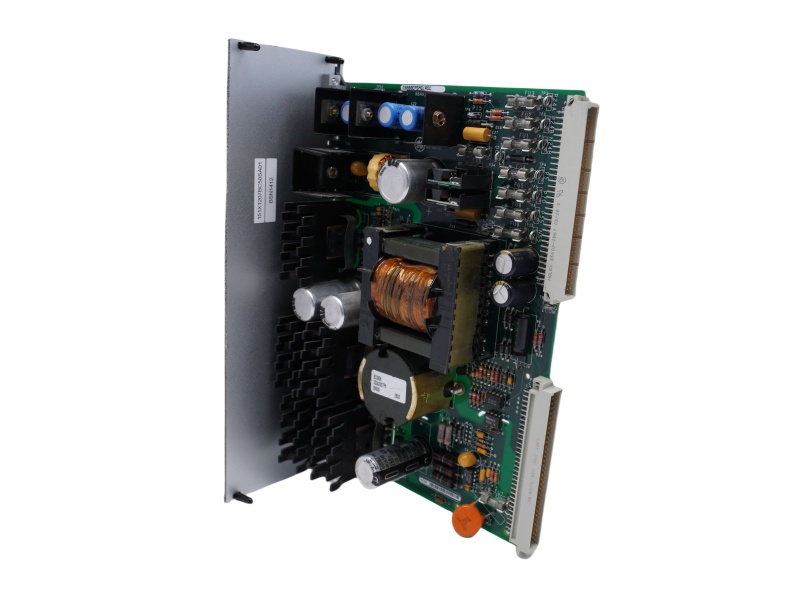
The 'full' side of the EX2100 Excitation Control IS200EMCSG1AA board contains important elements like an inductor coil, multiple electrolytic and ceramic capacitors, and polyester vinyl capacitors. This side also features six heat sink components, strategically arranged in two rows, ensuring effective thermal management. The resistors used in the IS200EMCSG1AA are primarily metal film, contributing to the board’s overall reliability and performance. Additionally, the IS200EMCSG1AA includes a relatively low number of integrated circuits, focusing instead on the reliability of discrete components.
Shipping options for the GE Speetronic MKVI IS200EMCSG1AA are flexible to accommodate various needs, whether requiring expedited or economical delivery. AX Control offers tailored shipping choices, ensuring that each customer can select the best option for their specific requirements. The IS200EMCSG1AA Mark VI PCB Board Assembly is an essential part of the IS200EMCSG1AA Gate Drive Power Supply Board, with detailed product revision tables and protective coatings, making it a reliable and versatile component for your systems.
If you have other request contact our team to get customized service


 Call +86 18159889985 to be connected with our Manager Stella
 Email to sales6@apterpower.com get your best quotation
 For the quick assistance message us on WhatsApp at +86 18159889985 now!
|
GE |
IS200EMCSG1AAB |
GE |
IS220YDOAS1AJ |
GE |
IS200VAICH1DAA |
|
GE |
IS420UCSBH3A |
GE |
IS200JPDMG1ADC |
GE |
IS200MVRBH1ACC |
|
GE |
IS200TRLYH1BED |
GE |
IS200SRLYH2AAA |
GE |
IS220PAOCH1BE |
|
GE |
IS200TRLYH1BGG |
GE |
IS200SRTDH2ACB |
GE |
IS420ESWBH2A |
|
GE |
IS200TRLYH1BGE |
GE |
IS200SRLYH2AAA |
GE |
IS220PDIAH1A |
|
GE |
IS200TRLYH1BGF |
GE |
IS220PRTDH1A |
GE |
IS220PAOCH1A |
|
GE |
IS200TRLYH1BEC |
GE |
IS220YDIAS1AK |
GE |
IS215VPROH1BE |
|
GE |
IS200EXAMG1A |
GE |
IS200TBAIS1CED |
GE |
IS215VPROH1BH |
|
GE |
IS200TREGH1BDB |
GE |
IS200TRLYS1BGG |
GE |
IS200TDBSH2AAA |
|
GE |
IS200TREGH1B |
GE |
IS200VAICH1D |
GE |
IS200VAICH1DAB |
GE Gas Turbine Control System
The GE Mark VI system is a comprehensive control solution used primarily in power generation and other industrial applications. It controls, protects, and monitors gas and steam turbines, generators, and auxiliary systems.
The SPEEDTRONIC™ Mark VI turbine control is the current state-of-the-art control for GE turbines that have a heritage of more than 30 years of successful operation. It is designed as a complete integrated control, protection, and monitoring system for generator and mechanical drive applications of gas and steam turbines. It is also an ideal platform for integrating all power island and balance-of-plant controls. Hardware and software are designed with close coordination between GE’s turbine design engineering and controls engineering to insure that your control system provides the optimum turbine performance and you receive a true “system” solution. With Mark VI, you receive the benefits of GE’s unmatched experience with an advanced turbine control platform.
The heart of the control system is the Control Module, which is available in either a 13- or 21- slot standard VME card rack. Inputs are received by the Control Module through termination boards with either barrier or box-type terminal blocks and passive signal conditioning. Each I/O card contains a TMS320C32 DSP processor to digitally filter the data before conversion to 32 bit IEEE-854 floating point format. The data is then placed in dual port memory that is accessible by the on-board C32 DSP on one side and the VME bus on the other. In addition to the I/O cards, the Control Module contains an “internal” communication card, a main processor card, and sometimes a flash disk card. Each card takes one slot except for the main processor that takes two slots. Cards are manufactured with surface-mounted technology and conformal coated per IPC-CC830. I/O data is transmitted on the VME backplane between the I/O cards and the VCMI card located in slot 1. The VCMI is used for “internal” communications between:
■ I/O cards that are contained within its card rack
■ I/O cards that may be contained in expansion I/O racks called Interface Modules
■ I/O in backup <P> Protection Modules
■ I/O in other Control Modules used in triple redundant control configurations
■ The main processor card
Triple Redundancy
Mark VI control systems are available in Simplex and Triple Redundant forms for small applications and large integrated systems with control ranging from a single module to many distributed modules. The name Triple Module Redundant (TMR) is derived from the basic architecture with three completely separate and independent Control Modules, power supplies, and IONets. Mark VI is the third generation of triple redundant control systems that were pioneered by GE in 1983. System throughput enables operation of up to nine, 21-slot VME racks of I/O cards at 40 ms including voting the data. Inputs are voted in software in a scheme called Software Implemented Fault Tolerance (SIFT). The VCMI card in each Control Module receives inputs from the Control Module back-plane and other modules via “its own” IONet. Data from the VCMI cards in each of the three Control Modules is then exchanged and voted prior to transmitting the data to the main processor cards for execution of the application software. Output voting is extended to the turbine with three coil servos for control valves and 2 out of 3 relays for critical outputs such as hydraulic trip solenoids. Other forms of output voting are available, including a median select of 4-20ma outputs for process control and 0- 200ma outputs for positioners. Sensor interface for TMR controls can be either single, dual, triple redundant, or combinations of redundancy levels. The TMR architecture supports riding through a single point failure in the electronics and repair of the defective card or module while the process is running. Adding sensor redundancy increases the fault tolerance of the overall “system.” Another TMR feature is the ability to distinguish between field sensor faults and internal electronics faults. Diagnostics continuously monitor the 3 sets of input electronics and alarms any discrepancies between them as an internal fault versus a sensor fault. In addition, all three main processors
continue to execute the correct “voted” input data,More info pls check GEH-6005 datasheet