T8461 Product datasheet
|
Model number: |
T8461 |
|
Module Type: |
Digital Output Module |
|
Manufacture: |
Rockwell |
|
Condition: |
Brand New |
|
Range of Product: |
Trusted TMR System |
|
Lead time: |
In Stock |
|
Weight: |
1.7 kg |
|
HS CODE: |
8537101190 |
|
Dimension: |
39x31x9cm |
|
MOQ: |
1 |
|
Product Origin: |
USA |
|
System: |
PLC |
|
Discontinued on: |
active |
|
Communication Service: |
Ethernet router |
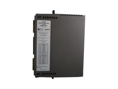
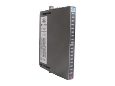
T8461 Functional Description
Experience unparalleled reliability with the T8461 Digital Output Module from ICS Triplex, expertly designed for demanding industrial environments. This cutting-edge Triplex Digital Output Module offers a high number of outputs, making it the perfect solution for complex control systems that require precision and durability.
If you have other request contact our team to get customized service


 Call +86 18159889985 to be connected with our Manager Stella
 Email to sales6@apterpower.com get your best quotation
 For the quick assistance message us on WhatsApp at +86 18159889985 now!
|
ICS Triplex |
T3480 |
ICS Triplex |
T8850C |
ICS Triplex |
T8431 |
|
ICS Triplex |
T3420A |
ICS Triplex |
T8850 |
ICS Triplex |
T8403 |
|
ICS Triplex |
T3419 |
ICS Triplex |
T8830C |
ICS Triplex |
T8311 |
|
ICS Triplex |
T3411F |
ICS Triplex |
T8830 |
ICS Triplex |
T8310C |
|
ICS Triplex |
T3401 |
ICS Triplex |
T8800 |
ICS Triplex |
T8232 |
|
ICS Triplex |
T3310 |
ICS Triplex |
T8480 |
ICS Triplex |
T8151B |
|
ICS Triplex |
T9432 |
ICS Triplex |
T8461CX |
ICS Triplex |
T8122 |
|
ICS Triplex |
T9451 |
ICS Triplex |
T8461C |
ICS Triplex |
T8110B |
|
ICS Triplex |
T9310-02 |
ICS Triplex |
T8461 |
ICS Triplex |
T7481A |
|
ICS Triplex |
T9300 |
ICS Triplex |
T8431C |
ICS Triplex |
T3481A |
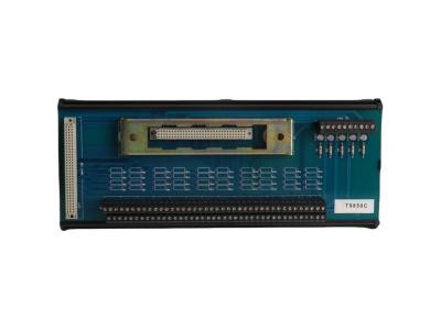
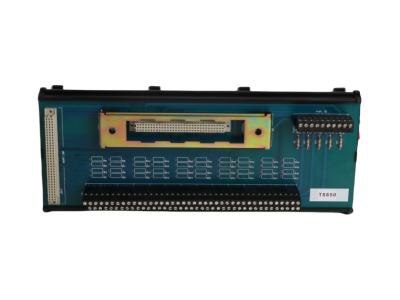
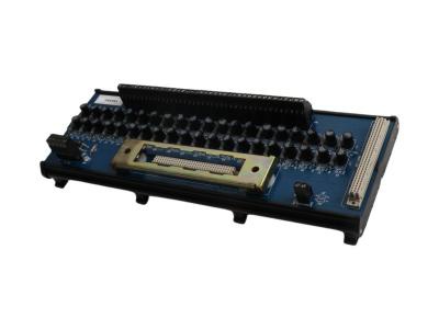
Trusted 40 Channel Analogue or Digital Output FTA
The Trusted® 40 Channel Analogue Output or Digital Output Field Termination Assembly (FTA) is designed to act as the main interface between the Trusted Triple Modular Redundant (TMR) 24 Vdc Digital Output Module T8451, Trusted Triple Modular Redundant (TMR) 24/48 Vdc Digital Output Module T84611 or Trusted TMR Analogue Output Module T8480 and the field device.
Recommended proof test methods
Calibration check procedure:24V DC digital outputs
Step A - Set the current to the AI channel 4 mA, verify that the input value is in the range -41 to +41 counts.
Step B - Set the current to the AI channel 12 mA, verify that the input value is in the range 2007 to 2089 counts.
Step C - Set the current to the AI channel 20 mA, verify that the input value is in the range 4055 to 4137 counts.
Step D – Return to Specific Method.
This test is required for all 24V DC DO modules or DC powered NO Contact where Normally De-energized (Energize to Trip) channels (T8850 when used with the T8451, T8461, or T8891 when used with the T8842) are used for Safety-Related Outputs used where the Proof Test frequency >> frequency of Demands. The purpose of this test is to verify that the diodes used for OR’ing the two Field Power sources are not Open circuit, therefore does not constitute a potential undetected dangerous failure. The method described here is the recommended method to verify that neither of the diodes used to OR the 24V DC field supply to a specific T8850 FTA, or the DC supply feeding NO Contact outputs is open circuit. It is assumed that this methodology will be incorporated into a Proof Test procedure that includes other elements of Proof Testing and general proof test requirements as defined in IEC61511.
Method:
Step 1 - If performing this test on a live system, it may be necessary to employ a method external to the Trusted logic solver to mechanically or electrically force any Normally Energized (De Energize to Trip) outputs associated with final elements on the FTA under test into their normal operating state. If not, proceed to Step 2.
Step 2 – Turn off the ‘A’ field supply at an appropriate isolation or termination point and verify that the diode related to ‘B’ supply is correctly providing 24V DC to each power group on the FTA under test.
Step 3 – Return the ‘A’ field supply into service.
Step 4 – Turn off the ‘B’ field supply at an appropriate isolation or termination point and verify that the diode related to ‘A’ supply is correctly providing 24V DC to each power group on the FTA under test.
NOTE: Although strictly NOT required from a Proof Test perspective, a secondary test can be performed while the ‘A’ Power source is turned off (disconnected) to verify that the diode associated with the ‘A’ supply is not ‘Short Circuit’. With 1k ohm resistor connected in series with the meter, measure the current (in mA) from the supply side of the diode to 0V and the current should be << 24 mA if the diode is correctly preventing backfeed of the ‘B’ supply (there will be a small leakage current, so it may not be 0 mA).